Tuesday, September 25, 2012

Konstanta gas


Konstanta gas
Konstanta gas (disebut juga konstanta gas ideal, molar, semesta, atau universal, biasanya dilambangkan dengan huruf R) adalah sebuah konstanta fisika yang sering muncul dalam banyak persamaan fundamental fisika, seperti hukum gas ideal dan persamaan Nernst. Konstanta ini ekuivalen dengan konstanta Boltzmann, tetapi dinyatakan dalam satuan energi per kelvin per mol (daripada energi per kelvin per partikel).
Harganya adalah:
R = 8.314472(15) J · K-1 · mol-1
Dua digit di dalam kurung adalah ketidakpastian (deviasi standar) pada harga dua digit terakhir.
Konstanta gas didapatkan dari persamaan keadaan paling sederhana, hukum gas ideal, sebagai berikut:
P = \frac{nRT}{V} = \frac{RT}{V_{\rm m}}
dengan:
P\,\!adalah tekanan absolut
T\,\!adalah temperatur absolut
V\,\!adalah volume "ruang" yang ditempati
n\,\!adalah jumlah gas (jumlah molekul gas, biasanya dalam mol)
V_{\rm m}\,\!adalah volume molar

Friday, July 27, 2012

MERUBAH MP3 KE WAV

Sambil iseng coba MP 3 di HP, kaga jalan-jalan buka internet ketemu tu software untuk mengubah MP3 jadi WAV, akhirnya enjoy dengerin .........hp.
link nya ada disini, silakan download

Thursday, July 26, 2012

Simple switch-Off Time Delay Circuit


Designing a switch off delay circuit is quite simple and will cost you no more than $5 to make. All parts can be picked up from Radio Shack or Fry's if you have them as well as Parts Express. This will cover the mechanical aspects of it - theoretical topics can come later. If you suffer from pops on your amps or any other components, this will help you eliminate it, but it does not work in all cases.
Simple switch-Off Time Delay CircuitSimple switch-Off Time Delay Circuit

Designing a swictch off delay circuit is quite simple and will cost you no more than $5 to make. All parts can be picked up from Radio Shack or Fry's if you have them as well as Parts Express. This will cover the mechanical aspects of it - theoretical topics can come later. If you suffer from pops on your amps or any other components, this will help you eliminate it, but it does not work in all cases.

The two circuits di atas illustrate opening a relay contact a short time after the ignition or ligh switch is turned off. The capacitor is charged and the relay is closed when the voltage at the diode anode rises to 12 volts. The circuit on the left is a common collector or emitter follower and has the advantage of one less part since a resistor is not needed in series with the transistor base. However the voltage across the relay coil will be two diode drops less than the supply voltage, or about 11 volts for a 12.5 volt input. The common emitter configuration on the right offers the advantage of the full supply voltage across the load for most of the delay time, which makes the relay pull-in and drop-out voltages less of a concern but requires an extra resistor in series with transistor base. The common emitter (circuit on the right) is the better circuit since the series base resistor can be selected to obtain the desired delay time whereas the capacitor must be selected for the common collector (or an additional resistor used in parallel with the capacitor).

The time delay for the common emitter will be approximately 3 time constants or 3*R*C. The capacitor/resistor values can be worked out from the relay coil current and transistor gain. For example a 120 ohm relay coil will draw 100 mA at 12 volts and assumming a transistor gain of 30, the base current will be 100/30 = 3 mA. The voltage across the resistor will be the supply voltage minus two diode drops or 12-1.4 = 10.6. The resistor value will be the voltage/current = 10.6/0.003 = 3533 or about 3.6K. The capacitor value for a 15 second delay will be 15/3R = 1327 uF. We can use a standard 1000 uF capacitor and increase the resistor proportionally to get 15 seconds.

Source: bowdenshobbycircuits.info

Regulator Variable Sederhana

A simple but less efficient method of controlling a DC voltage is to use a voltage divider and transistor emitter follower configuration. The figure below illustrates using a 1K pot to set the base voltage of a medium power NPN transistor.

Rangkaian Regulator Variable SederhanaSkema Rangkaian Regulator Variable Sederhana

The collector of the NPN feeds the base of a larger PNP power transistor which supplies most of the current to the load. The output voltage will be about 0.7 volts below the voltage of the wiper of the 1K pot so the output can be adjusted from 0 to the full supply voltage minus 0.7 volts. Using two transistors provides a current gain of around 1000 or more so that only a couple milliamps of current is drawn from the voltage divider to supply a couple amps of current at the output.

Note that this circuit is much less efficient than the 555 timer dimmer circuit using a variabe duty cycle switching approach. A fairly large heat sink is required to prevent the PNP power transistor from overheating. The advantage of the circuit is simplicity, and also that it doesn't generate any RF interference as a switching regulator does. The circuit can be used as a voltage regulator if the input voltage remains constant.

Wednesday, July 25, 2012

220V AC Ultra Bright LEDs lamp Circuit

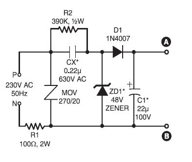
This ultra-bright white LED lamp works on 230V AC circuit with minimal power consumption. Ultra-bright LEDs available in the market cost Rs 8 to 15. These LEDs emit a 1000-6000mCd bright white light, like the welding arc and work on 3 volts, 10 mA. Their maximum voltage is 3.6 volts and the current is 25 mA. Anti-static precautions taken Pls Should Be handling the LEDs. The LEDs in a water-clear plastic package emit spotlight, while diffused type LEDs have a wide-angle radiation pattern.
220V AC Ultra Bright LEDs lamp Circuit220V AC Ultra Bright LEDs lamp Circuit

The schematics circuit of above employs capacitive reactance for limiting the current flow through the LEDs on the application of mains voltage to the circuit. We use only if a series resistor for limiting the current with mains operation. The 100-ohm, 2W resistor series avoids heavy 'inrush' During current transients. MOV at the input prevents surges or spikes, protecting the circuit. The 390-kilo-ohm, ½-watt resistor acts as a bleeder to Provide discharge path for capacitor Cx Pls mains supply is disconnected. The zener diode at the output section prevents excess levels of reverse voltage appearing across the LEDs During the negative half-cycles. During the positive half cycle, the voltage across the LEDs is limited to the zener voltage.
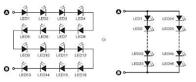
220V AC Ultra Bright LEDs lamp Circuit16-LED/46-LED combination

Aseries combination of 16 LEDs Gives a luminance (lux) equivalent of a 12W bulb. But if you have two series combinations of 23 LEDs in parallel (Total 46 LEDs), it Gives equal to a 35W light bulb.

Diode D1 (1N4007) and capacitor C1 act as rectifying and smoothing elements to Provide DC voltages to the row of LEDs. For a 16-LED row, use Cx of 12:22 μF, 630V; C1 of 22 μF, 100V; and zener of 48V, 1W. Similarly, for 46 LEDs combination use Cx of 0:47 mF, 630V; C1 of 33 μF, 150V; and zener of 69V, 1W. This circuit (inclusive of LEDs) costs Rs 200 to Rs 400.

10 LED VU Meter Using IC LM3914


This 10 LED VU meter circuit has only a few parts but is useful as an indicator for the measurement of entering acoustic signals. The circuit is a perfect one chip replacement for the standard analog meters. It is completely solid state and will never wear out
LM3914 VU Meter Circuit

The circuit is built around an LM3914 IC. The input signal from the VU meter is put on pin 5 of IC1. Through pin 9 of IC1 is the display mode sets (bar or dot instructions). In the drawn state IC1 works in the dot mode. When pin 9 is coupled to pin 3, the IC works in bar mode. Obviously the whole circuit consumes less power in dot mode.

List Component
C1        : 2.2uF/ 25V Electrolytic Capacitor
R1        : 1K  Resistor
D1        : 1N4002 Diode
LED1-LED  : 10 x  LED or LED Array
U1        : LM3915 
 
Notes
  • V+ can be anywhere from 3V to 20V. 
  • The input is designed for standard audio line voltage with has a maximum input voltage of 1.3V.
  • Pin 9 can be disconnected from ground to make the circuit use a moving dot display instead of a bar graph display.

Light/Dark Switch With Relay


Thursday, May 19, 2011

Light/Dark Switch With Relay

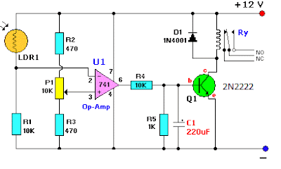
The circuit as shown act as a light detector. Under normal conditions the resistance of the LDR is high, keeping pin 2 low. When light falls onto the LDR the resistance drops to a couple hundred ohms and triggers pin 2 high which biases the base of Q1 via pin 6 and R4 and in turn activates the relay.

Light/Dark switch with relayLight/Dark switch Circuit with relay

As you may have notice, the 741 is connected as a voltage comparator. Two voltage dividers are easy to be found: The first one is the10K resistor and the LDR . The second one is composed by the two 470 Ohms resistors and the potentiometer. Both the outputs of the dividers are connected as inputs to the voltage comparator.

The second voltage divider will settle the reference voltage. The first voltage comparator that contains the LDR, will change it's voltage according to the light level. When the voltage across the negative input of the comparator is less than the voltage to the positive input of the comparator, the output is held low. When the voltage on the negative input rises, there will be a time that it becomes greater than or equal to the positive (pre-selected) voltage, and then the output becomes high and the relay through the 2N2222 is actuated.


Showing posts with label Adaptor/ Regulator. Show all posts

Tuesday, December 28, 2010


Rangkaian Regulator Variable Sederhana


Regulator Variable SederhanaA simple but less efficient method of controlling a DC voltage is to use a voltage divider and transistor emitter follower configuration. The figure below illustrates using a 1K pot to set the base voltage of a medium power NPN transistor.Skema Rangkaian Regulator Variable SederhanaThe collector of the NPN feeds...

Friday, December 25, 2009


Rangkaian Power Supplay


Electronic devices should be powered by direct current supply DC (direct current) which is stable in order to work properly. The battery or batteries is a source of DC power supply is best. But for applications that require greater power supply, the source of the battery is not enough. Sources of power supply is a source of alternating AC...

Tuesday, December 22, 2009


1.25V-15.19V Regulator/Adaptor Variabel Digital


Rangkaian Regulator/Adaptor Variabel DigitalThis is a series regulator with variable output from the digital 1.25V to 15.19V The first section of the circuit comprises a digital up-down counter built around IC1, a quad 2-input NAND Schmitt trigger (IC CD4093), followed by IC2, a binary up-down counter (CD4029 IC). Two gates of IC CD4093...

Sunday, December 20, 2009


Rangkaian USB Power Boster (USB Adaptor )


USB Power Boster (USB Adaptor )USB can be configured for connecting several peripheral devices to a single PC, Since a PC can supply only a limited power to the external devices connected through its USB port, when too many devices are connected simultaneously, there is a possibility of power shortage, Therefore an external power source...

Thursday, December 17, 2009


Regulator 5 volt Meggunakan IC 7805


Regulator 5 volt IC 7805The IC 7805 provides circuit designers with an easy way to regulate DC voltages to 5v. Encapsulated in a single chip/package (IC), the 7805 is a positive voltage DC regulator that has only 3 terminals. They are: Input voltage, Ground, Output Voltage.Skema rangkaian regulator 5 voltLayout IC 7805Although the 7805 were...

Wednesday, December 16, 2009


Adaptor 12 volt menggunakan 2n3055


Rangkaian Adaptor 12 volt 2n3055This adapter circuit can deliver up to 3A at 12V output voltage. The circuit can be employed on occasions when a current of more that 3A is demanded for regulator. IC regulators of such high current rating are pretty hard to find.The transformer T1 steps down mains voltage, to 12rms & the rectifier bridge...


+12Volt|-12Volt Dual Regulator Power Supplay


This is of a dual regulated that provides +12V and -12V from the AC mains. A regulator like this is a very essential tool on the work bench of an electronic hobbyist.Transformer T1 steps down the AC mains voltage and diodes D1, D2, D3 and D4 does the job of rectification. Capacitors C1 and C2 does of filtering.C3, C4, C7and C8 are decoupling...

Wednesday, October 14, 2009


Rangkaian Car Regulator Converter


This is car regulator 12 VDC to 9 VDC converters side for audio, playstation,DVD,etc... The regulator designed for 12DC to 9DC converters that we bring to our design circuit . They are all effective in Switch Mode Power Supplies regulated output. We have developed a series of DC-DC power supply models ranging from 1 watt to 500 watts,...

Monday, August 17, 2009


Rangkaian +5V Switching regulator


Rangkaian +5V Switching regulator used LM2575-5.0. You can make the stable voltage by using the 3 terminal regulator like LM317. However, because the output electric current and the inputted electric current are the same approximately, the difference between the input electric power (The input voltage x The input electric current) and the...

Friday, August 14, 2009


Rangkaian Regulator menggunakan Op-Amp


Regulator is a series of regulations or the voltage output from power so that a portion darinaik effects or voltage drop in net does not affect the voltage ration power to be so stable.Regular circuit of regulators have been good if the ripple voltage is small, but there is a problem of stability. If the voltage PLN rise /down, then the...

Wednesday, August 12, 2009


Rangkaian Regulator menggunakan Diode Zener


Regulator is a circuit of regulations or the voltage output from a ration resources so that the effects of increased tension or decrease in net does not affect the voltage ration power to be so stable.Rangkaian Dasar Regulator Diode ZenerSimple circuit regulator , working on the zener breakdown voltage so that it produces the same output...

Saturday, July 18, 2009


Variable Adaptor ( 3 , 4 , 5, 9, 12 sampai 37 volt)


Variable Adapter (3 , 4 ,5 ,9 ,12 ,16 ,20 to max 37 volt)The LM117 series of adjustable 3-terminal positive voltage regulators is capable of supplying in excess of 1.5A over a 1.2V to 37V output range. They are exceptionally easy to use and require only two external resistors to set the output voltage. Further, both line and load...

Sunday, May 10, 2009


Power supplay (Adapter)


12 volt dual voltage of adapterTransformator 18v-CT (min)Capasitor 35vBridge Rectifier 2 Ampere /100 vc4, c5 Ceramic12 VOLT 20 Ampere of adapterUsing a single 7812 IC voltage regulator and multiple outboard pass transistors, this power supply can deliver output load currents of up to 20 amps. ...

Thursday, February 19, 2009


ADAPTOR 12 VOLT 20 AMPERE


Now it should not have to wrestle again seek op-amp, transistor and other components to realize a massive circuit of regulators, because the circuit of this kind have been packed into a fixed voltage regulator IC. Currently, many components known as the 78XX series fixed positive voltage regulator and the 79XX series is a voltage regulator...

220V AC Operated Christmas Light Star Circuit

220V AC Operated Christmas Light Star Circuit

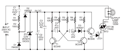
Here is a simple circuit of Christmas light star that can be easily constructed even by a novice. The main advantage of this circuit is that it doesn’t require any step-down transformer or ICs.
220V AC Operated Christmas Light Star CircuitCircuit of 220V AC Operated Christmas Light Star

Components like resistors R1 and R2, capacitors C1, C2, and C3, diodes D1 and D2, and zener ZD1 are used to develop a fairly steady 5V DC supply voltage that provides the required current to operate the multivibrator circuit and trigger triac BT136 via LED1. The multivibrator circuit is constructed using two BC548 transistors (T1 and T2) and some passive components. The frequency of the multivibrator circuit is controlled by capacitors C4 and C5 and resistors R3 through R7. The output of the multivibrator circuit is connected to transistor T3, which, in turn, drives the triac via LED1. During positive half cycles of the multivibrator’s output, transistor T3 energises triac BT136 and the lamp glows. This circuit is estimated to cost Rs 75.

Note:
This circuit directly connected to the netting of electricity, voltage 220V electricity it could sting you. Avoid working in damp and directly with ground

Circuit Design By: PRINCE PHILLIPS
Source: www.electronicsforu.comwww.electronicsforu.com

Hukum Hukum Rangkaian Teknik Elektro

Hukum Kirchoff Arus|Kirchoff tegangan
- Hukum Kirchoff ArusStates that "all the algebraic number of the flow enters a knot / point in the series is a zero" or "the amount of flow that enters the knot in a series with the same amount of flow that is out of the knot."Expressed mathematically withAs an illustration shown in the picture below:So based on the law applicable kirchof...
READ MORE...

Hukum Ohm

Hukum OhmStates that "the voltage across the various types of materials are proportionate with the straight flow of the stream." Mathematically expressed by:Ohm's law formula can be derived as follows:V is the voltage (in volt), I is the current that flows (in ampere) and R is resistansi or obstacles (in ohm, Ω) which is 1 ohm value is equal...
READ MORE...

Arus |Tegangan|Daya||Energi Listrik

Arus listrik|Electric current (I)Electric current states that the number of load flow in a certain direction on a series of electrical elements of each unit of time. Mathematically expressed by:with,I: electric current (in ampere)Q: electric load (in coulomb)t: time (in seconds)Than the electric current magnitude have also have a direction...
READ MORE...

Analisis Nodal/Simpul/Titik -Analisa Rangkain Elektronika

Analisis Nodal/Simpul/Titik Untuk mempermudah Analisa Rangkain ElektronikaNodal / Simpul /titik Analysis By using this method, we will first obtain the size of the voltage on each of a series in which later can be used to explore the amount of electricity the other.Stages to implement a Nodal / Simpul / Titik Analysis is this:1. Determine...
READ MORE...

Tuesday, July 21, 2009

Analisis Loop/Mesh Pada Rangkaian Elektronika

Analisis Loop/Mesh Pada Rangkaian ElektronikaStages to implement the Loop Analysis / Mesh is this:1. Determine the direction of flow in each loop in the series. Usually selected with the clockwise direction.2. Determine the polarity of each element in the series.a. In the source: cash flow from the polarity (-) to the polarity (+)b. In the...
READ MORE...

Transformasi Sumber

Transformasi Sumber When we apply a method to analyze a series of DC, may be necessary to change the source of flow into voltage source or voltage source into a source flow.Not any source can be transformed. A voltage source in series with the new resistans can be transformed into a source of flow in parallel with resistans. Instead of a...
READ MORE...

Teorema Thevenin - Analisis Rangkaian Elektronika

Teorema Thevenin untuk menganalisis Rangkaian DCThevenin theorems states that any two of the series can be converted into an equivalent set of which consists of a voltage source thevenin (ETH) and a resistans equivalent thevenin (RTH) is in series with voltage source thevenin.Steps to find the rope thevenin is:1. Specify two of the series...
READ MORE...

Teorema Norton-Analisis Rangkaian Listrik

Teorema Norton untuk menganalisis Rangkaian listrik DCNorton theorems is that, any two of the series can be converted into an equivalent set of which consists of a current source (IN) and a norton equivalent resistans (RN) with a source flow dipararel it.Steps to find the rope it is:1. Specify two of the series who want to search string...
READ MORE...